

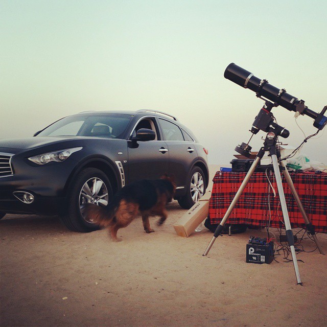
After a couple of years of doing Astrophotography from the roof of my house, I grew tired from the constant packing and unpacking of my astro gear. It takes about half an hour to assemble all the equipment, and about another half an hour to disassemble and store back into their respective boxes. While the occasional trip to AlSalmy desert, about an hour drive from where I live, is worthwhile with its spectacular dark sky, nothing beats of the convenience of a home observatory.
Moreover, since I am the developer of Ekos, and the primary developer of INDI, I frequently need to test changes in the INDI drivers and Ekos framework or to try out new astro gear, and this required even more dedicated time in setting the equipment for testing purposes. Therefore, the idea of a permanent observatory began to constantly invade my mind. However, due to the complexity of such a task and the financial budget required to complete it, I put it on hold for the last couple of years.

In August of 2015, I finally received pending payments from a car insurance company for an accident that occurred the prior year. I took this as an opportunity to build my dream observatory, especially given the fact that I worked heavily in the development of Ekos Scheduler which is tailored to observatory automation. A completely automated Linux powered observatory is about to become a reality. Most home observatories are built using a rolloff roof, it is not only cheaper but it is mechanically simpler compared to a dome and requires less maintenance. However, one stark difference is that the majority of rolloff observatories are built with wood structure in mind, where all structures in Kuwait are a concrete/steel based; wood is seldom used. Therefore, the design would have to be tailored not only to account the material differences, but also to withstand extremely hot temperature reaching up to 60 degrees Celsius (140 F) under direct sun light in the summer months
Location-wise, I did not have much choice. The house roof seemed the most suitable place with the greatest sky clearance. In Kuwait and neighboring countries, houses are constructed of concrete unlike their European and American counterparts. Given the old architecture of the house, I decided to build a rather spacious observatory (by amateur astronomers standards) on the roof. The roof measures 3.4x6.1 meters with 1.5m high walls.
After some initial planning, I came up with a preliminary CAD design that included the following:
- Reserve a spacious 3.4x4.3 meter area to house the observatory equipment.
- Raise the wall height from 1.5m to 2.0m: The 50cm increase in height was to block more stray street light, house my pier+telescope combination comfortably, and to allow me to move around within the observatory without hindrance. The observatory gear might be upgraded in the future, so more space is always welcome.
- Mount 4 steel beams on each corner and then the metal roll-off structure rests on it. Few additional steel columns should support the roll-off roof at the back side when retracted.
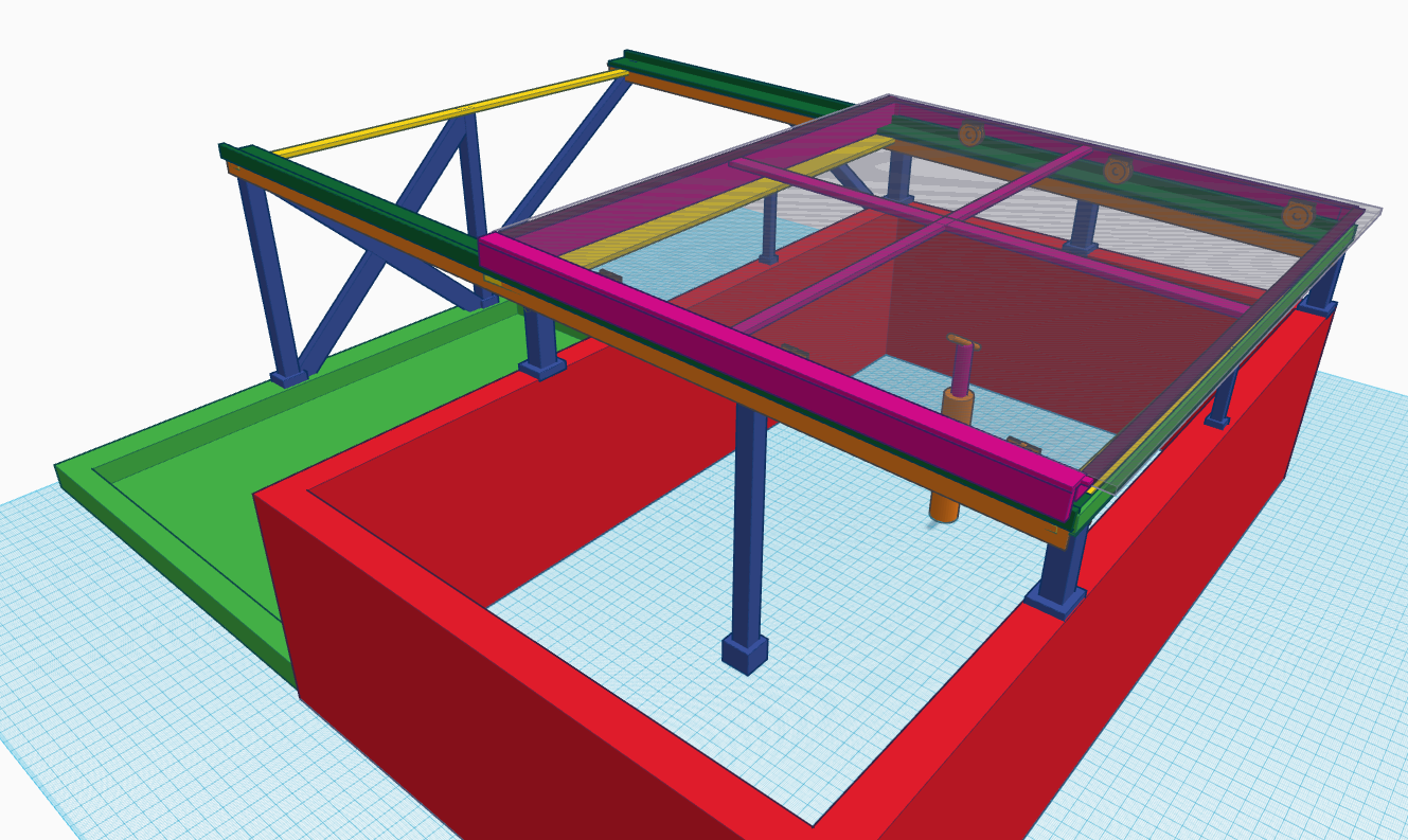
- Build a concrete pier 105cm in height with a 20 cm diameter. The mount shall be secured to Dan's Pier Plate for HEQ5 mount. The base plate shall be anchored within the concrete via 12" L style anchor bolts. The pier column shall be constructed on a 50cm x 50cm concrete slap.
- Construct a stationary 9x4.5 m steel frame, and a mobile 4.0x4.5m frame to hold the roof on four wheels on each side.
- Mount a ~4.0x5.0m sandwich panel with 7cm of insulation material to protect the observatory assets during Kuwait summer heat and against rain and dust.
The construction timeline proceeded as following:
October 6th, 2015
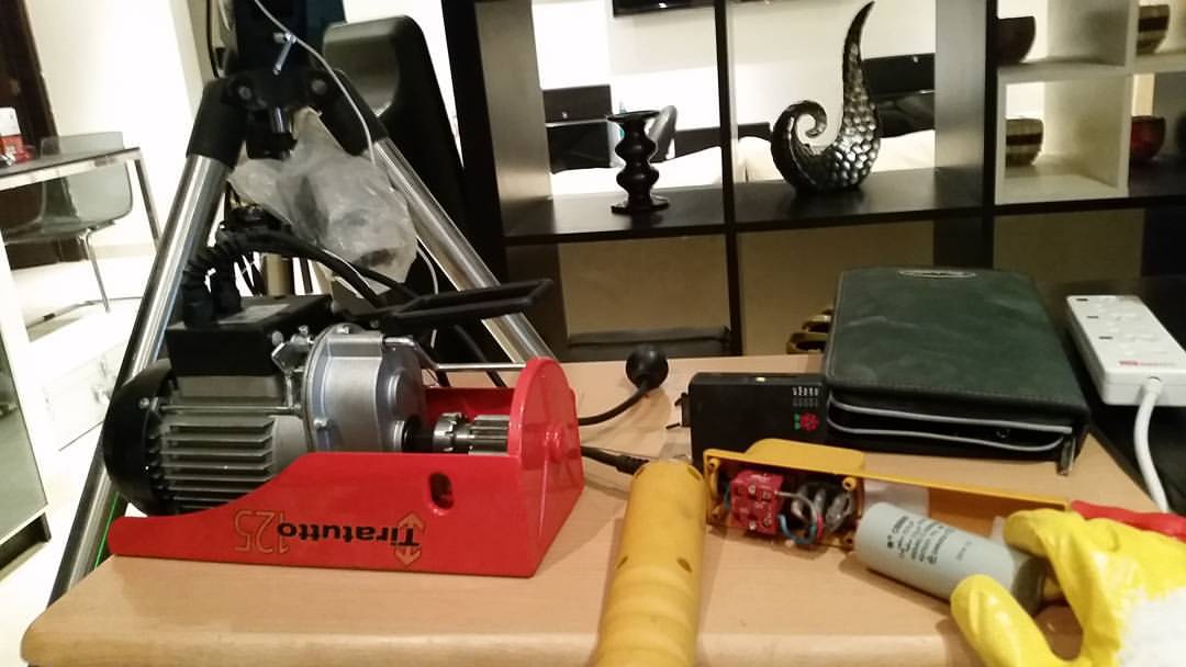
Given the size and material of the roof material, a 0.5 HP motor was estimated to be sufficient to move the roof on the 9 meter long tracks. Since 3-phase AC motors and reversible DC motors can be quite expensive (~$1000) in Kuwait, I opted for an electric winch motor that can be adapted for my purposes. A local hardware store carried $150 Chinese winch motors which seemed to fit the bill. The motor comes with a pendant switch which is compromised of a rocker switch, an emergency stop switch, and a dual start/run capacitor. With remote control in mind, the motor was wired to a remotely controlled din relay via to the pendant switch. The motor comes with a circuit diagram that made this hack quite straightforward. The rocker switch controls the flow of electricity from mains and unto the motor windings. Since it is a single phase induction motor, a capacitor serves as a phase-shifter (Current leads voltage) and this phase difference induces the rotating magnetic field necessary for motion. The winch cable was of no use and was removed and a spur gear was installed instead. The spur gear is designed to mesh with a gear rack that would be attached to the roof to achieve motion.
The motor also comes with two limit switches which are intended to stop the winch from hitting its designated travel limits. After removing the built-in limit switches, I re-wired the circuitry to my two external limits switches, which would be placed at the the extreme travel limits of the rolloff roof once installed.
October 8th, 2015
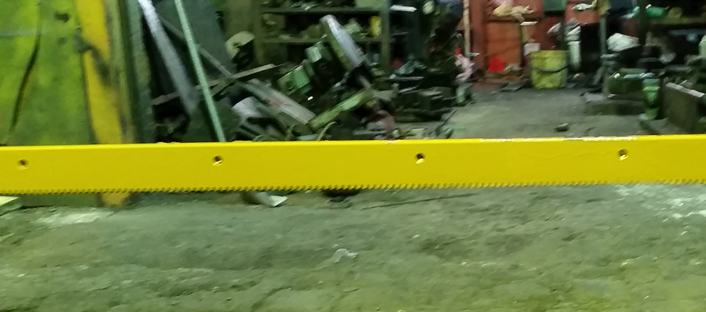
Machined a 4.5m long gear rack at a local machine shop. The gear rack shall be bolted to the roof and meshed with the motor spur gear.
October 9th, 2015
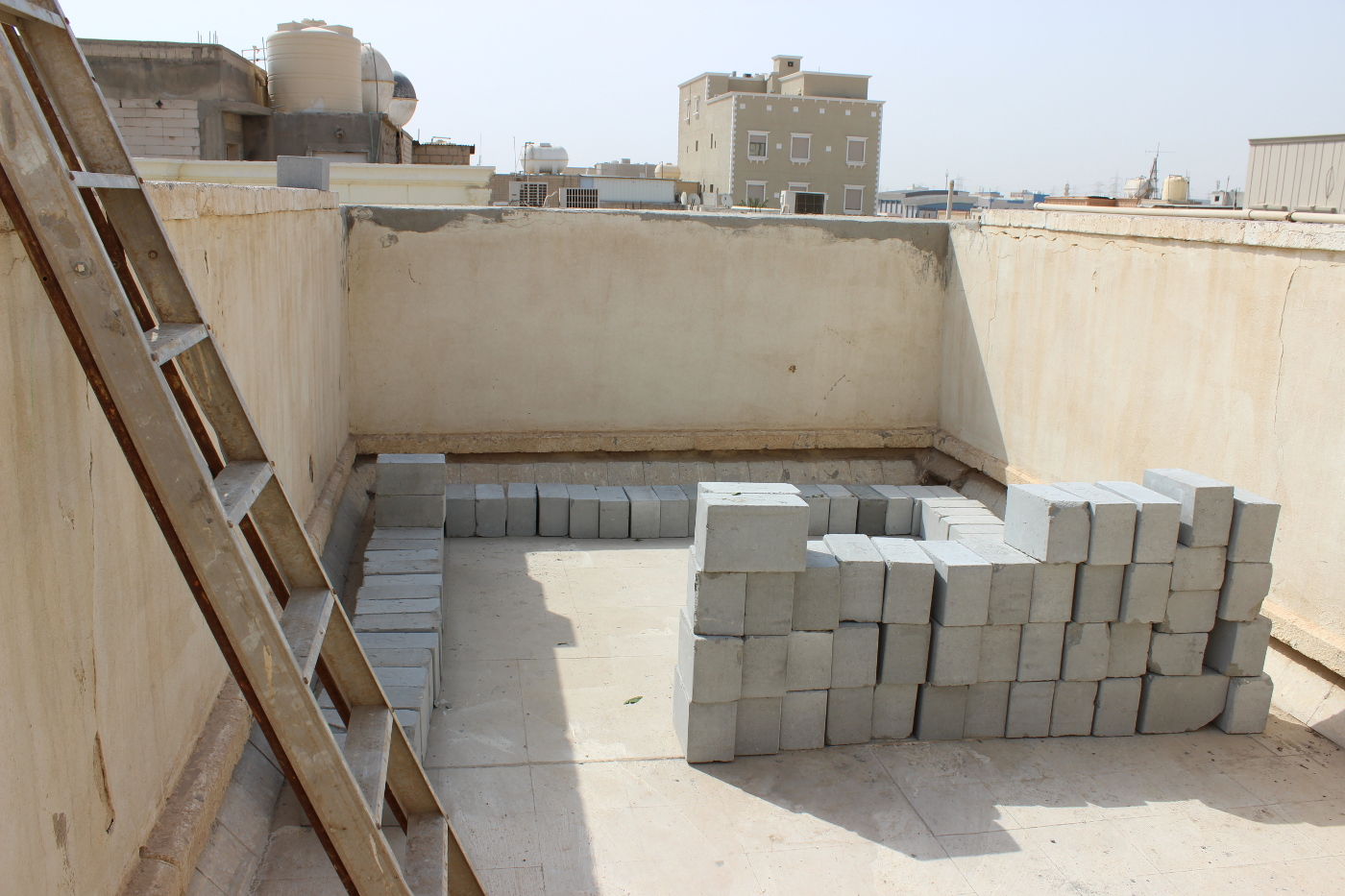
A couple of friends, one of whom is an Architect, suggested that I do not need to start with the 50cm steel beams on the wall corners as originally envisioned in the CAD design as the wall should be able to carry all the weight without any issues. So I went with their proposal (which I later found to be problematic) and thus construction works began on Oct. 9th. Several meters of heavy black bricks were hauled to the roof. In Kuwait, brickwork is mainly done with either heavy black 40x20x20 cm bricks, or lite-weight heat resistant 60x20x20 white bricks. Due to the heavy metal structure, I initially decided to go with all black bricks in order to support the weight.
October 11th, 2015
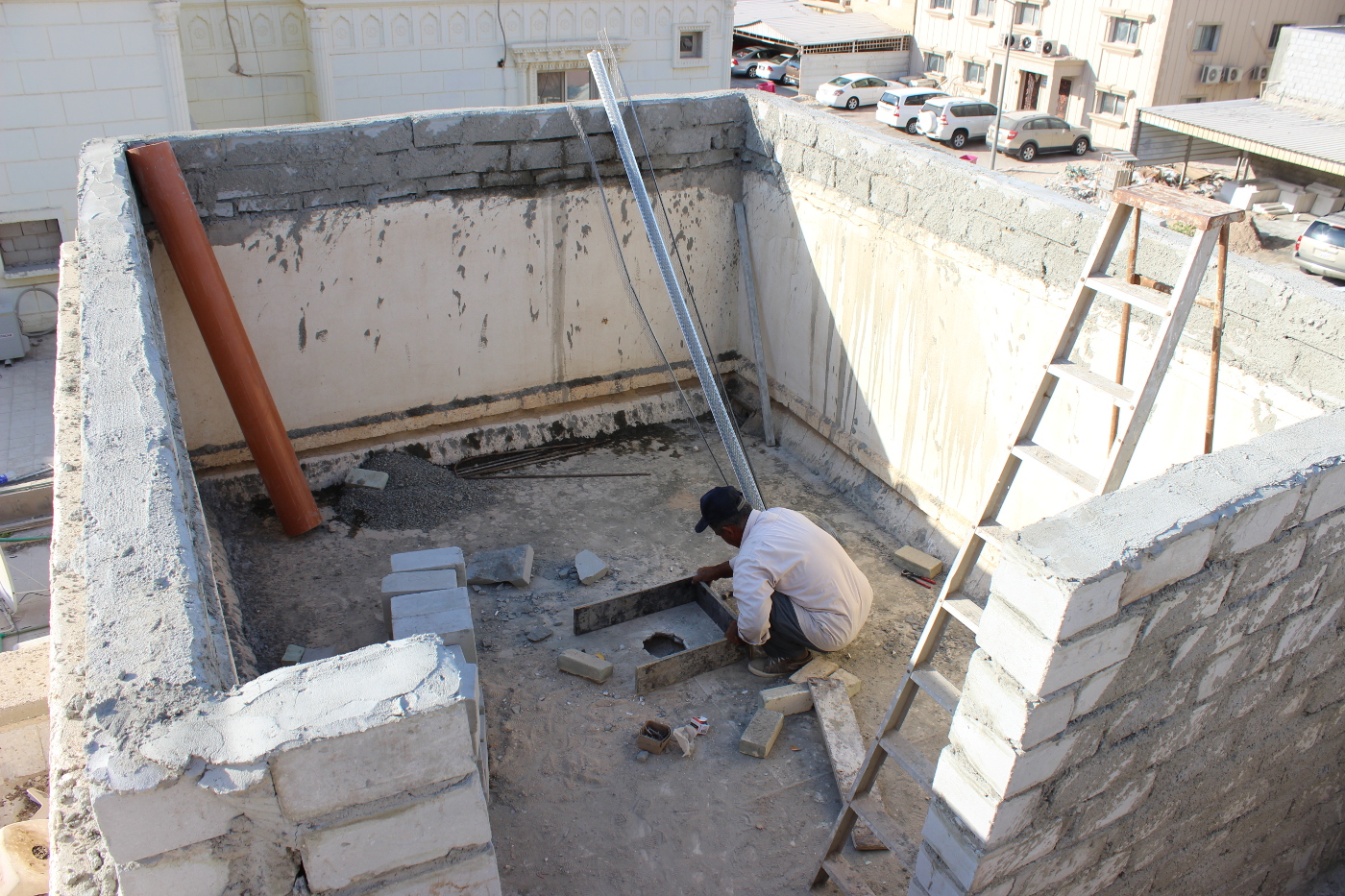
Side walls are raised to 2m and the north observatory wall is constructed with a 1m opening for the observatory door. During this period, I was not able to directly supervise the construction process due to work so the contractor responsible for the construction process at the site. A 50x50 cm concrete slap was poured at the center of the observatory with 4 iron beams. It was left to cure for a few days before pouring the concrete for the pier column.
October 14th, 2015
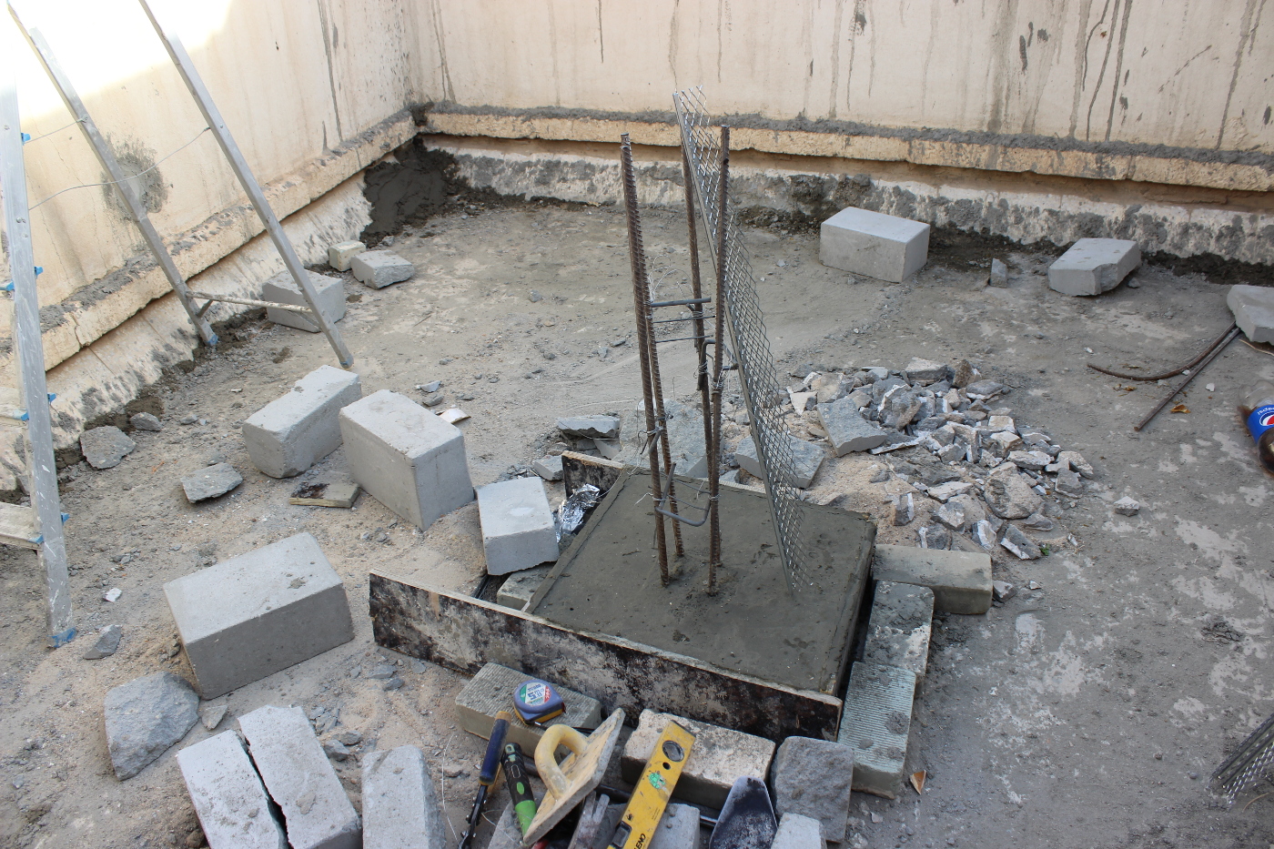
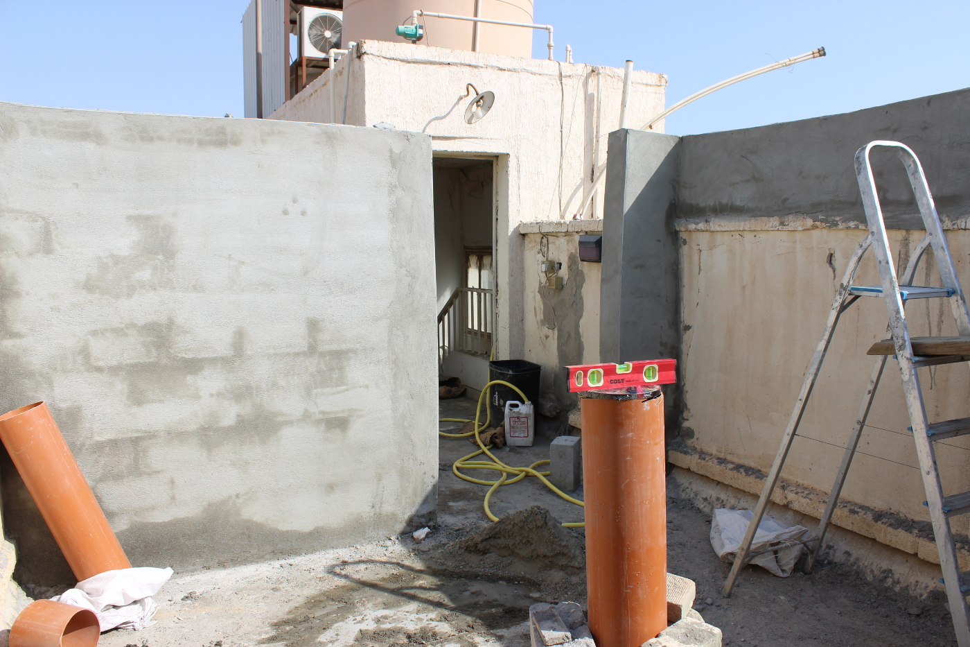
Before applying a coated layer on the brick wall, reinforced mesh was nailed to enable the application of multi coated layer of cement, gravel, and sand to complete the external finishing of the walls. After the initial coating was complete, the contractor, being the jack of all trades, cut an 8" PVC pipe to the desired pier height of 105cm, however, the cut was not level and was done quite poorly. The base plate from Dan's Pier Plates was anchored within the concrete pier, and the base plate was adjusted to ensure it is level. But this marked one of the many problems in the construction process. The north wall was only leaning but was mis-aligned as well, again due to the contractor's poor construction process. Furthermore, the pier column was leaning by about 7 degrees! The base pier plate was still perfectly level, but the column pier itself was slightly leaning. At this time, I pondered on how to fix these issues, and given the contractor sloppy job, I stopped any further works by him and decided to take time off work to be able to supervise any construction works directly.
October 22nd, 2015
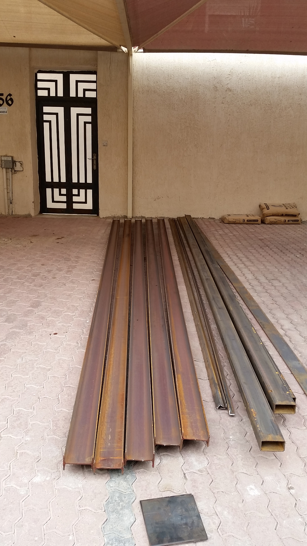

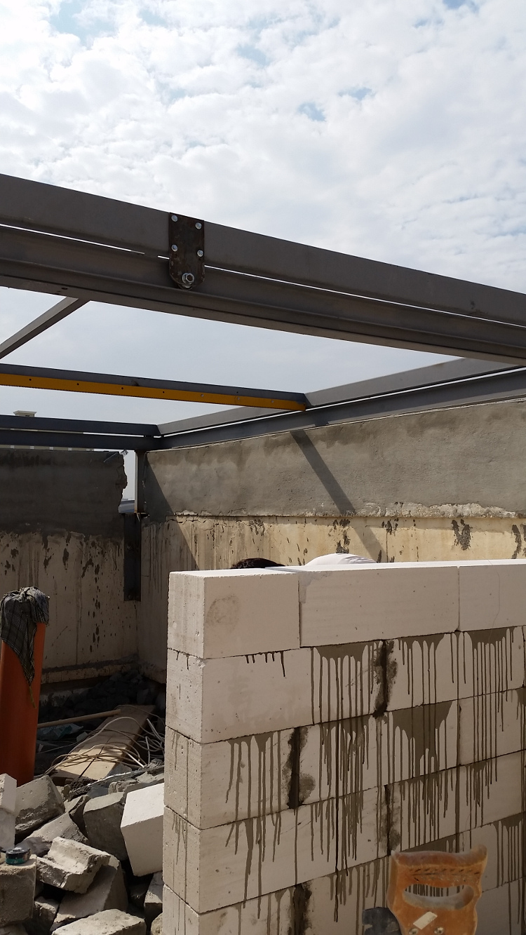
After the issues with the walls and pier, it was time to go back to the original CAD design where the steel structure is first constructed followed later by the brickwork. A local welder was hired to construct the rolloff structure along with the sandwitched roof. Steel beams arrived shortly and they were painted a metalic grey. The welder said it wouldn't be possible to support the steel structure weight with only the wall strength. So we went back to the original CAD design and proceeded. Four steel bases were bolted on the wall corners and the leaning walls were demolished.
October 25th, 2015
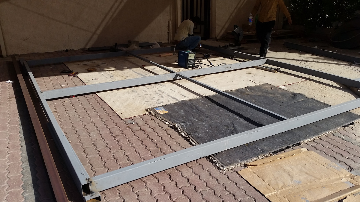
The rolloff frame construction began at the ground floor. The gear rack was cut and bolted to the steel frame.
October 26th, 2015
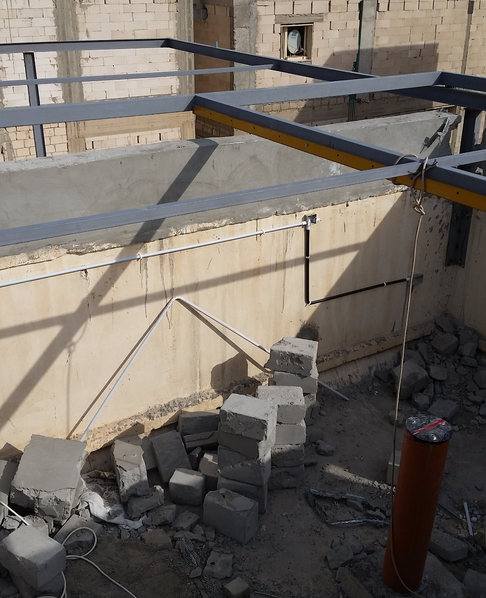
The rolloff frame construction completely rather quickly and a crane hauled it to the roof. The mobile frame is resting on the stationary frame with the support of 4 wheels on each side.
October 27th, 2015
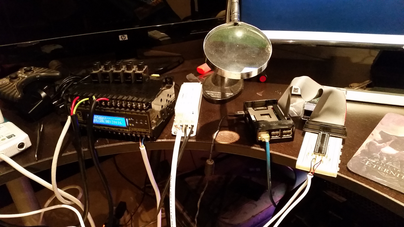
Since the control software needs to know the status of the roof on startup, that is whether the roof is parked (fully closed) or unparked (fully open) or somewhere in the middle. Thanks to the suggestions of the users in the All About Circuits forum, I added two limit switch sensors by connecting wires from the limit to a cheap phone charger. The limit switches are Normally Closed (NC), which means that unless actuated, the limit switch should carry the mains 240v power back to the motor. Hence, a wire from each limit switch is connected to a phone charger that would bring the voltage down a manageable 5 VDC. Since the Raspberry PI2 GPIO operate at 3.3v logic, a simple 2-resistor voltage divider brought the voltage down to the Pi2 GPIO range. When the Pi2 GPIO is HIGH, this indicates that the limit switch is NOT actuated, and once it is LOW, then it indicates that the limit switch was actuated resulting in the power cut. Now the INDI rolloff driver would be able to know the parking status on startup and detect parking/unparking changes whenever they occur.
November 1st, 2015
As the steel structure is able to withstand the roof weight, I opted for the lite heat resistant white bricks for the observatory's north wall. Construction began and this time I supervised the work very closely to insure all goes accordingly to plan.
November 2nd, 2015
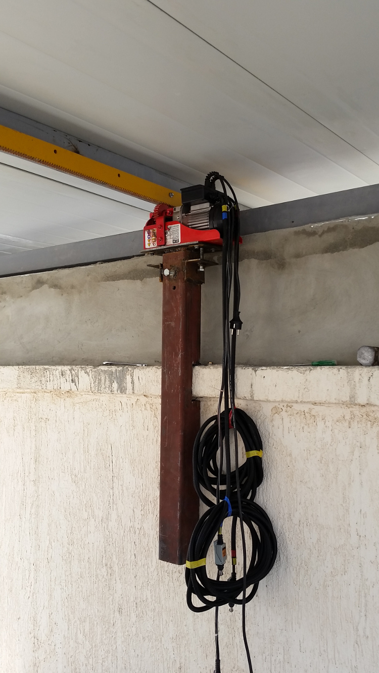
Initial work to mount the motor also began and this is when we discovered a problem with the motor height as we could not mesh the spur gear with the gear rack as the motor controls were housed on the top of the motor in a box which in turn collides with the mobile roof. I paid another visit to the local machine shop and machined another spur gear, double the diameter of the initial gear, was installed meshed with the original gear. This would result in halving the speed, but also doubling the torque which is more important. Furthermore, I used a smaller box with minimal connectors and rerouted all the other connectors for the pendant switch, limit switch, and their sensors elsewhere to minimize the size of the box.
November 4th, 2015
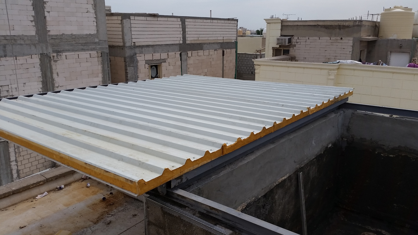
Sandwich panel arrived and hauled to the roof to be bolted on the mobile frame. To make the observatory rain and air tight, especially with the occasional dusty weather we get in Kuwait, the roof was fitted with rubber panels to seal the observatory. The winch motor was re-mounted and initial testing was successful! It was an amazing moment to see the mobile roof in motion.
November 9th, 2015
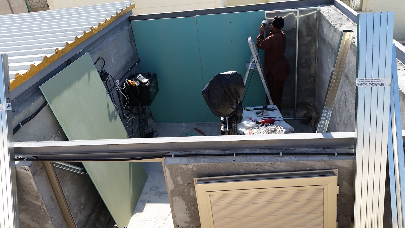
Application of coating to the wall to complete the finishing. Usually after the rough coat is applied, a finer coat is applied before the final paint job is done, but I opted to install gypsum boards instead of painting the walls, so the rough coat was sufficient.
November 14th, 2015
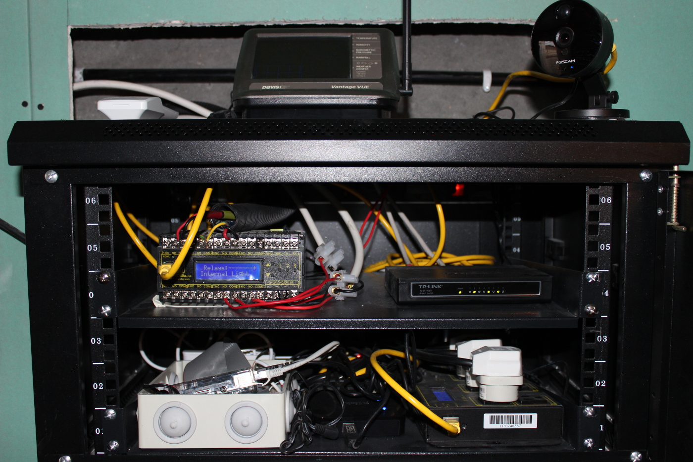
Began working on mounting the control cabinet within the observatory and installing the equipment. The following is a list of the cabinet equipment:
- TP-Link 8 port gigabit switch
- Digital Loggers Din Relay: It controls the roof motor, AC unit, and internal light
- Raspberry Pi2 along with voltage dividers connected to the phone chargers. The chargers are connected to the limit switches to detect if they are actuated or not.
- Powered USB hub: The hub is connected to Pi2 and the following devices:
- Orion Sirrus EQ-G (HEQ5) Mount.
- QSI 583wsg CCD with 5-position internal filter wheel.
- MoonLite focuser.
- Lodestar x2 autoguider.
- Optec FlipFlat for remotely controlled dust cover and flat field source.
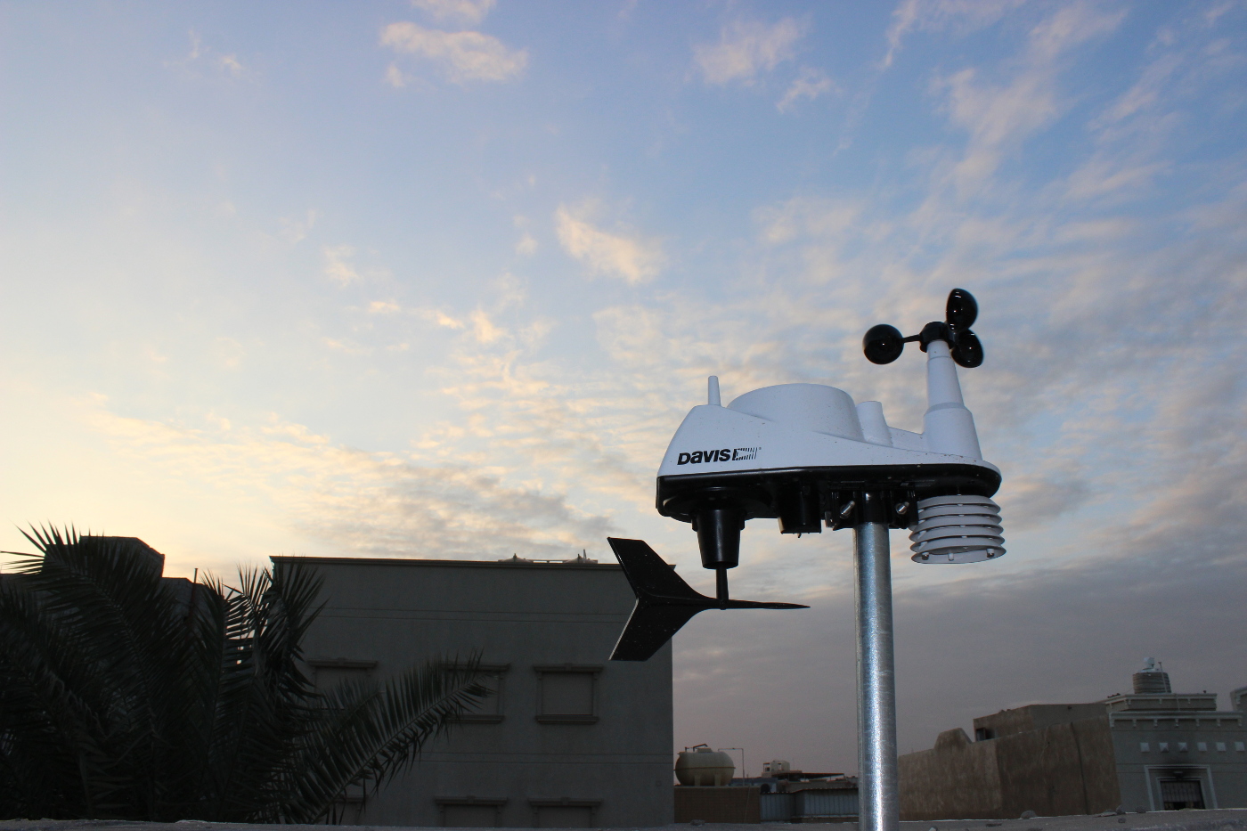
- Davis Instrument Vantage Vue weather station serial console.
- Digital Loggers Power Switch: It controls power to the mount, CCD, and focuser.
Two Foscam IP cameras were installed within and outside the observatory for monitoring purposes. They are equipment with night vision capability via infrared light.
November 19th, 2015
Gypsum boards were mounted to a lite alumunim structure bolted on the observatory walls. Furthermore, an alumunim door was installed thereby sealing the observatory. The Davis Instruments Vantage Vue weather station was mounted close to the observatory.
November 21st, 2015
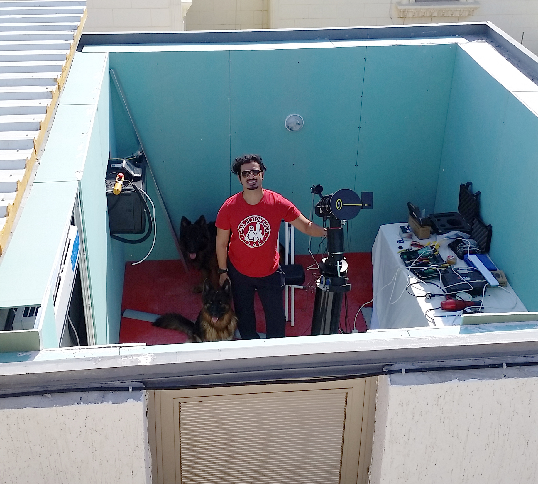
Hard-plastic flooring tiles are laid in the observatory and all equipment are installed and wiring complete! The mount, CCD, and focuser all require 12v power supply, but the manufacturer supplied power supplies were quite short. Due to the distance from the pier to the control cabinet, I had to utilize three laptop chargers with 3 Amps supply and extended their length to 5 meter long. A 24,000 BTU air conditioner unit was installed as it is critical especially during the summer months to keep the observatory equipment at acceptable temperature settings. Lots of clean up took place to remove dust and other particles from the observatory.
First light of the observatory was performed and all equipment are operating perfectly!